- PRODUCTS
-
- CNC Metal Cutting Equipment
- Cylinder Processing Equipment
- Round Bar Peeling Machine
- Straightening Machine
- Chip Handling Equipment
- Polishing Machine
- Surface Grinder
- Electroplating Equipment
- Drawing Machine
- CNC Machining Center
- Center-less Grinding Machine
- Production Line
- Cylinder Processing
- Rolling Mill
- Free Forging Machine
- Chamfering&Facing Machine
- Heat Treatment Machine
- Vacuum pump
- Application
- Contacts Us
-
Mobile +8618663896299
-
Fax +86-535-6896668
-
E-mail: haige@haigechina.com
CNC Vertical Machining Center
Home>PRODUCTS>CNC Machining Center>CNC Vertical Machining Center
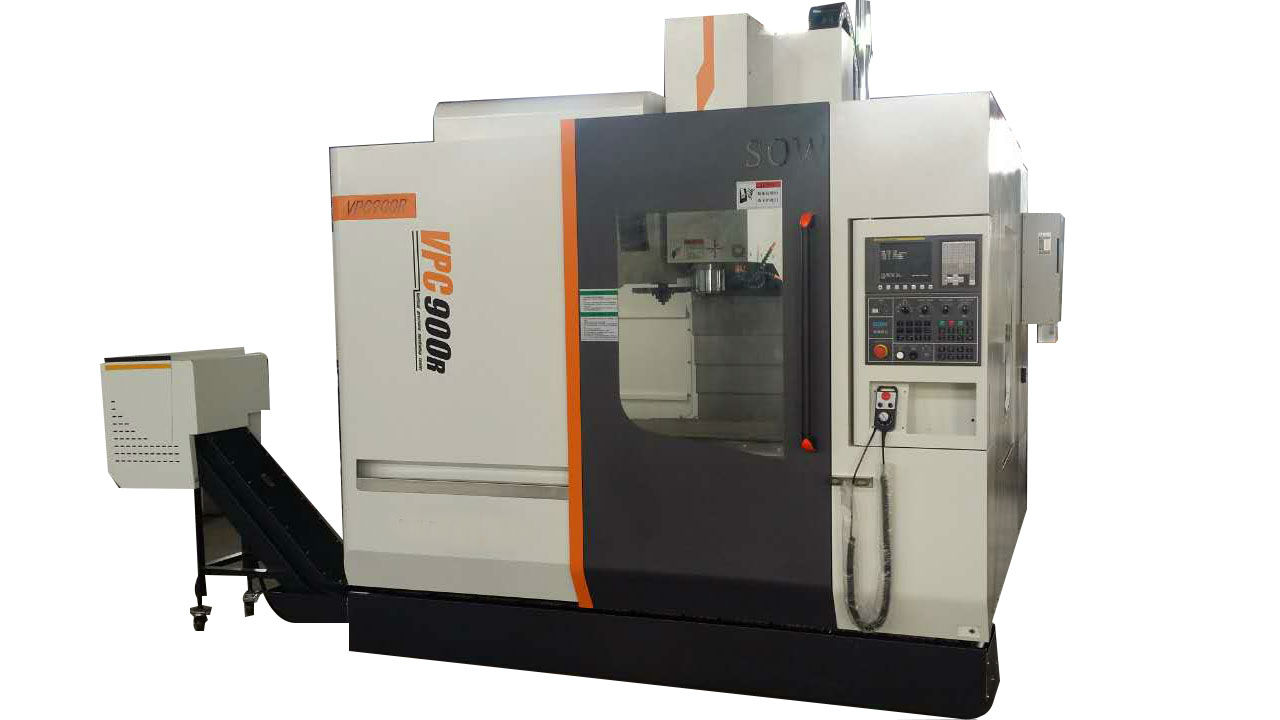
VPC1100H High Speed Vertical Machining Center
Detailed Introduction
VPC1100H high-speed vertical machining center is a high-tech product of mechanical and electrical integration, developed by our company on the basis of absorbing advanced technology domestically and abroad. The product can perfectly achieve high-speed processing through the breakthrough of speed and precision combination technology, and it can complete the milling, drilling, tapping and surface machining. VPC900R is highly automatic and can be widely used in electronics, instrumentation, automobiles, motorcycles, military, medical equipment and other fields. Its main features are as follows:
1.1 The machine tool base castings (including bed, column, bed saddle, spindle box and table, etc.) are made of high-strength cast iron material and casted in the resin sand production line. They are of high mechanical stability and thermal stability. The machine tool adopts bed body structure and thin-walled & multi-bar structure in which the bars are arranged reasonably. This improves the unit mass stiffness of casting, and that’s why the rigidity of the machine tool is good.
2.1 The machine adopts high strength synchronous belt for the drive from the digital AC spindle servo motor to the spindle, which can drive with good rigidity and high accuracy. The maximum speed of a standard spindle is 10000rpm.
2.2 The spindle components are of high precision and high rigidity; the spindle bearings are import brand.
2.3 Adopt butterfly spring to achieve the tool tension and pneumatic hydraulic cylinder loosing tool.
2.4 The vertical movement adopts high-power and high-torque motor to achieve high-speed response.
2.5 Optionally, the machine tool can be equipped with spindle oil cooler, which can effectively solve the spindle the temperature rise in high-speed operation.
3 Feed Drive
3.1 The AC servo motor and the ball screw are directly linked by coupling to reduce the transmission stages and improve response speed of the movement. The couplings are imported, with high strength and small inertia, to reduce the rotation inertia.3.2 The ball screw nut was pre-tightened to reduce the gap between the nut and the raceway.
3.3 All the three feed shafts adopt high-precision laser interferometer after assembly which can accurately measure the transmission link error and make compensation for the screw pitch and clearance in the system so that the shafts move their positions more accurately to ensure the accuracy of positioning and repeated positioning.
3.4 The three-way feed applies linear roller guide (width 30 mm). The span of the guide rail is large, taking into account the carrying capacity and making the machine response speed better.
4 Lubrication System
4.1 The lubrication system is equipped with a centralized lubrication device, which regularly and quantitatively lubricates the guide rail and ball screw.4.2 The lubrication flow and lubrication time has been adjusted before leaving factory, so the user does not need to change them by himself.
4.3 The automatic and centralized lubrication device has alarm system, which works when the oil level is lower than the set value. At this time, the user needs to add lubricants timely.
5 Machine Cooling, Chip Removal
5.1 The work piece and the machine tool are cooled by high pressure spray coolant. Large flow of coolant is sprayed to cool the tool and the work piece during machining.5.2 Optionally, the machine can be equipped with automatic chip removal device, so that chip removal is more convenient.
6 Pneumatic System
6.1 The FR&L are standard configuration to filter the impurities and moisture in order to prevent damage and corrosion by the impurities.6.2 The functions of the pneumatic system are controlled by PLC program through solenoid valve.
6.3 The spindle power source for tool release and air blowing is compressed air.
7 Machine Protection
7.1 Adopt a special guide rail protection hood or other effective protection method in the machining area.7.2 The machine is surrounded by a closed shield, with beautiful appearance, clean and tidy.
7.3 The guide rail protection hood guarantees that the cooling liquid and iron chips will be safely and adequately recycled.
8 Machine Tool Library
The machine adopts advanced arm locking library with 24 tools. The tool change is completed by mechanical arm, fast and reliable.9 Control System
9.1 The machine is configured with FANUC-0I-MF system and its supporting drive, which has reliable performance and full-function, and is easy to maintain.9.2 The machine has a handheld operating unit, with user-friendly operation.
9.3 The main electrical components of the machine are Siemens brand, improving the reliability of electrical control.
9.4 The machine is configured with a standard 8.4-inch color display, with beautiful interface, simple and convenient operation.
9.5 The electrical control cabinet is equipped with air conditioner for constant temperature to ensure the stable operation of the system.
10 Optional CNC Turntable
10.1 Optionally, the machine can be equipped with vertical and horizontal dual-use CNC turntable to constitute the fourth axis, which coordinates with the CNC system to achieve four-axis four linkage function to further expand the machine processing range.10.2 Optionally, the machine can also be equipped with double pendulum turntable, to constitute a five-axis machine, which can process complex surface parts.
10.3 The turntable can have pneumatic or hydraulic (air-hydraulic conversion) clamping function.
10.4 The specifications and parameters of the turntable conform to the data provided by the manufacturer.
Technical Parameter
Name | Unit | Specification | Remarks |
Worktable area (length × width) | mm | 1300×600 |
|
T-slot (slot number - slot width × spacing) | mm | 5–18×100 |
|
The maximum load of the worktable | kg | 800 |
|
Worktable longitudinal travel (X) | mm | 1100 |
|
Worktable Horizontal travel (Y) | mm | 600 |
|
Spindle box vertical travel (Z) | mm | 600 |
|
distance from spindle end to worktable surface | mm | 120~720 |
|
distance from spindle center line to stand rail | mm | 675 |
|
Main motor power (AC) | kW | 11/15 |
|
Main motor torque (AC) | Nm | 52.5/95.5 |
|
Spindle maximum speed | r/min | 10000 |
|
Spindle taper hole |
| 7:24 ISO40 |
|
Tool holder Type |
| BT40(MAS403) |
|
Feed rate: (X / Y / Z) | m/min | 30 |
|
Fast moving speed: (X / Y / Z) | m/min | 48/48/36 |
|
Tool library capacity | Piece | 24 | Arm lock type |
Tool selection |
| At will |
|
Tool changing time | Sec | 1.5 |
|
Maximum weight of tool | kg | 7 |
|
The maximum diameter of adjacent tool | mm | Φ75 |
|
Maximum tool length | mm | 300 |
|
Positioning accuracy (IS0 standard) | mm | 0.009 |
|
Repeat positioning accuracy (IS0 standard) | mm | 0.007 |
|
Machine weight | kg | About 7000 |
|
Machine dimensions (length × width × height) | mm | About 3100×2700×3100 |