- PRODUCTS
-
- CNC Metal Cutting Equipment
- Cylinder Processing Equipment
- Round Bar Peeling Machine
- Straightening Machine
- Chip Handling Equipment
- Polishing Machine
- Surface Grinder
- Electroplating Equipment
- Drawing Machine
- CNC Machining Center
- Center-less Grinding Machine
- Production Line
- Cylinder Processing
- Rolling Mill
- Free Forging Machine
- Chamfering&Facing Machine
- Heat Treatment Machine
- Vacuum pump
- Application
- Contacts Us
-
Mobile +8618663896299
-
Fax +86-535-6896668
-
E-mail: haige@haigechina.com
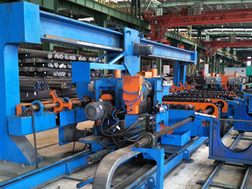
15-85mm Double heads chamfering&Facing machine
Detailed Introduction
Main part of the machine:Chamfering&adjustment device
Double-bar dual-end Chamfering&facing and double-end chip removal device and conveying rack are all installed on the same body. The bar material is loaded to the left end facing device or the right end facing device through the dialing device on the roller table alternately. Two bars roll and slide into the double-station positioning V-groove. There are pulleys under the inner side of the V-groove. The cylinder pushes the bar on the pulley to the positioning block. The press cylinder on the double-facing device head drives the double V-shape holder to clamp the bar. Driven by the oil cylinder,the facing tool process the end surface.The left and right double facing devices process alternately. The jacking cylinder mechanism lifts the bar and convey the bar for the next double chamfering process (double pre-positioned V groove). The bar material was lifted and slides down from the double pre-position slot to (the right ,the double-end chamfering v-groove), and the bar is pushed by the cylinder again to the right side of the double chamfering head. There is a positioning block in front of the head (pneumatic lifting block), the bar stops where the block positions, the block is lifted, and the pressure cylinder on the double chamfering head drives the double V-shaped clamp to clamp the right end of the bar and the double chamfering head begins the chamfering process. The bar material slides from the double chamfering V-groove on the right end and slides into the double chamfering V-groove on the left end, and pushes the bar on the pulley to the left double-chamfering head by the cylinder again. The left and right double-head chamfering is also processing alternately and repeatedly. The right machine head is fixed, the left head and the conveying rack are driven by hydraulic cylinders, which can be adjusted according to different bar materials, and the length of the bar to be processed can be adjusted on the operating table. Milled and chamfered products have no burrs and are smooth and flat. The milling depth of the end face can be adjusted from 3 to 5mm, and the chamfer size is 2 ~ 3 × 45 ° mm. The depth of the milling surface and the chamfer can be adjusted according to the actual situation of the incoming material. It is required that no new bending deformation should be caused to the bar during the processing.
The clamping fixture can be a semi-circular special fixture or a "double V" universal fixture. The upper fixture is driven downward by the hydraulic cylinder to clamp the bar, and the lower fixture is fixed. Each pair of clamps is made of special alloy material to avoid pinching the bar.
The turning and adjusting mechanism completes the milling and chamfering functions of the bar material. The depth of the milling and chamfering can be adjusted according to the actual situation of the input material. The tool-feeding method is driven by hydraulic cylinders. The feeding speed is gradually reduced after rapid feeding Fast forward. The milling cutter head is a circular multi-cutter head. The blade is an alloy triangular blade. The slow feeding speed when turning the workpiece reduces the resistance and load of the cutter head and prolongs the service life of the blade. For different materials and specifications of bar material. The drive uses a variable frequency motor. The speed is adjusted by adjusting the frequency of the frequency inverter that matches the variable frequency motor. The speed can be adjusted automatically by inputting material parameters through the HMI, plus manual fine adjustment. During the turning process, the rotation speed is stable and there are no vibration tool marks. Milling and chamfering tools holder adopt the modular standard conical holder design of CNC machine tools. One set of tools-assembly for a certain of specification bars, can be quickly replaced without the need to adjust the blades and tool holders (about 10mm range, need a set of triangular tools. 6 sets of tool holders are expected) ). When replacing the cutter head, the upper and lower double V-shaped clamps can also be quickly replaced accordingly. Various adjustments are simple and easy to operate, and the machine head is equipped with a safety cover for easy loading and unloading, which plays a role of safety protection. When milling and chamfering, compressed air is used to cool the cutter head, while the iron filings are blown off.
Technical Parameter
Main technical performance parameters:
Total power: 60KW
Processed product diameter range: Φ15-Φ85mm.
Processed product length range: 3000mm-7000mm
Speed of processed products: 10 ~ 20 pieces / min (The speed should slow down when process bars with high strength, high hardness, large milling depth and large chamfer depth, and larger diameter)
Dimensions of this equipment: 17482mm * 7034mm * 1340mm.