- PRODUCTS
-
- CNC Metal Cutting Equipment
- Cylinder Processing Equipment
- Round Bar Peeling Machine
- Straightening Machine
- Chip Handling Equipment
- Polishing Machine
- Surface Grinder
- Electroplating Equipment
- Drawing Machine
- CNC Machining Center
- Center-less Grinding Machine
- Production Line
- Cylinder Processing
- Rolling Mill
- Free Forging Machine
- Chamfering&Facing Machine
- Heat Treatment Machine
- Vacuum pump
- Application
- Contacts Us
-
Mobile +8618663896299
-
Fax +86-535-6896668
-
E-mail: haige@haigechina.com
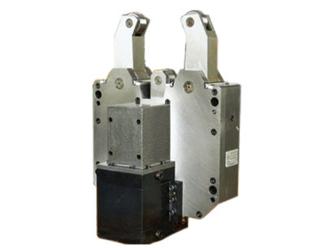
PK11U SERIES NC SELF CENTERING STEADY REST
Product introduction: The power part of the PK11U series center frame - the hydraulic cylinder is located on one side of the center frame body wall...
Detailed Introduction
The power part of the PK11U series center frame - the hydraulic cylinder is located on one side of the center frame body wall, which reduces the length of the center frame and is suitable for machine tools with smaller longitudinal dimensions at the center frame position.
Technical Parameter
| PK11U Main specification and parameter(mm) | |||||||||||||||
| Items Model | PK11 120x20U | PK11 140x40U | PK11 160x20U | PK11 160x60U | PK11 200x50U | PK11 235x35U | PK11 250x50U | PK11 270x50U | PK11 320x100U | PK11 350x220U | PK11 400x120U | PK11 400x260U | PK11 430x230U | PK11 460x200U | PK11 475x300U |
| Centering range | 20-120 | 40-140 | 20-160 | 60-160 | 50-200 | 35-235 | 50-250 | 50-270 | 100-320 | 220-350 | 120-400 | 260-400 | 230-430 | 200-460 | 300-475 |
| L1 | 356 | 398 | 409.5 | 389.5 | 465 | 466 | 544 | 593 | 615 | 603 | 788 | 697 | 697 | 803 | 770 |
| L2 | 247 | 298 | 307 | 282 | 365 | 295 | 368 | 433 | 454 | 455 | 587 | 520 | 520 | 610 | 569 |
| L3 | 85 | 100 | 96 | 96 | 125 | 125 | 128 | 156 | 180 | 180 | 210 | 205 | 205 | 240 | 250 |
| L4 | 50 | 33 | 41.5 | 46.5 | 15 | 76 | 78 | 48 | 20 | / | 41 | 22 | 22 | / | 5 |
| B1 | 280 | 310 | 330 | 330 | 380 | 438 | 400 | 446 | 460 | 460 | 600 | 550 | 570 | 600 | 686 |
| B2 | 160 | 180 | 180 | 180 | 220 | 200 | 240 | 310 | 300 | 300 | 380 | 370 | 370 | 380 | 500 |
| B3 | 130 | 125 | 117 | 117 | 157 | 120 | 120 | 160 | 165 | 165 | 168 | 168 | 168 | 200 | 200 |
| B4 | 253 | 305 | 278 | 278 | 368 | 366 | 405 | 466 | 493 | 513 | 592 | 633 | 633 | 705 | 688 |
| Y1 | 115 | 140 | 123 | 123 | 170 | 166 | 180 | 203 | 250 | 250 | 283 | 260 | 260 | 350 | 338 |
| Y2 | 150 | 165 | 180 | 115 | 190 | 135 | 210 | 230 | 270 | 220 | 330 | 300 | 300 | 310 | 370 |
| Y3 | 256 | 285 | 302 | 302 | 352/340 | 390 | 365 | 400 | 425 | 425 | 562 | 515 | 525 | 560 | 651 |
| M1 | 45 | 55 | 45 | 45 | 54 | 54 | 54 | 75 | 70 | 70 | 60 | 75 | 75 | 80 | 80 |
| M2 | 45 | 55 | 45 | 45 | 54 | 54 | 54 | 75 | 70 | 70 | 60 | 75 | 75 | 80 | 80 |
| M3 | 24 | 24 | 24 | 24 | 24 | 24 | 24 | 28 | 28 | 28 | 28 | 28 | 28 | 30 | 30 |
| U1 | 160 | 180 | 185 | 160 | / | 200 | 360 | 270 | / | 270 | 270 | / | 292 | ||
| U2 | 9 | 10 | / | / | / | / | 15 | 15 | / | 80 | 80 | / | 96.5 | ||
| H1 | 110 | 105 | 117 | 117 | 117 | 114 | 124 | 150 | 145 | 145 | 140 | 168 | 168 | 160 | 200 |
| H2 | 85 | 110 | 85 | 85 | 124 | 100 | 114 | 145 | 135 | 130 | 168 | 155 | 155 | 200 | 170 |
| J | / | / | 40 | 70 | 40 | 50 | 30 | 40 | / | 80 | 128x15" | 80 | 70 | 87.3x55" | / |
| D | 47 | 47 | 47 | 47 | 52 | 52 | 52 | 62 | 62 | 62 | 72 | 72 | 72 | 80 | 80 |
| T | 18 | 18 | 18 | 18 | 23 | 23 | 23 | 23 | 23 | 23 | 25 | 23 | 23 | 26 | 25 |
| d | / | / | 14 | 14 | / | 19.3 | / | / | / | 19.3 | / | 19.3 | 19.3 | / | / |
| P | 110 | 120 | 141 | 143 | 118 | 187 | 160 | 175 | 180 | 135 | 254 | 248.5 | 253 | 180 | 308 |
| Lubrication | 3-M8x1 | 3-M8x1 | 3-M8x1 | 3-M8x1 | 3-M8x1 | 3-M8x1 | 3-M8x1 | 3-M8x1 | 3-M8x1 | 3-M8x1 | 3-M8x1 | 3-M8x1 | 3-M8x1 | 3-M8x1 | 3-M8x1 |
| Inlet/Exhaust Holes | 2-G1/8" | 2-G1/8" | 2-G1/8" | 2-G1/8" | 2-G1/8" | 2-G1/8" | 2-G1/8" | 2-G1/8" | 2-M12x1.5 | 2-M12x1.5 | 2-G1/8" | 2-G1/8" | 2-G1/8" | 2-G1/8" | 2-G1/8" |
| Clampling/Loosen bore | 2-G1/4" | 4-G1/4" | 4-G1/4" | 4-G1/4" | 4-G1/4" | 4-G1/4" | 2-G1/4" | 2-G1/4" | 2-G1/4" | 4-G1/4" | 4-G1/4" | 4-G1/4" | 4-G1/4" | 4-G1/4" | 2-G1/4" |
| Maximum opening size | 126 | 146 | 160 | 160 | 225 | 231 | 276 | 282 | 350 | 353 | 400 | 418 | 432 | 480 | 477 |
| Interference circularity | 170 | 200 | 185 | 185 | 244 | 250 | 280 | 330 | 363 | 357 | 430 | 438 | 438 | 466 | 570 |
| Working pressure | 0.5-3 | 0.5-3 | 0.5-1.5 | 0.5-1.5 | 0.5-3 | 0.5-3.5 | 0.5-1.5 | 0.5-2.5 | 0.5-3 | 0.5-3 | 0.5-3 | 0.5-3 | 0.5-3 | 1.0-2.0 | 0.5-4 |
| Max clamping force | 5 | 5 | 4 | 3.2 | 5.16 | 7.5 | 5.7 | 8.5 | 9.5 | 8 | 9.5 | 14 | 14 | 10 | 11 |
| Accuracy of cenering | 0.04 | 0.05 | 0.05 | 0.05 | 0.05 | 0.05 | 0.05 | 0.05 | 0.05 | 0.05 | 0.05 | 0.05 | 0.05 | 0.05 | 0.05 |
| Accuracy of reorduction | 0.01 | 0.01 | 0.01 | 0.01 | 0.01 | 0.01 | 0.01 | 0.01 | 0.01 | 0.01 | 0.01 | 0.01 | 0.01 | 0.01 | 0.01 |
| Sheild | Y | Y | N | N | Y | Y | Y | Y | Y | Y | Y | Y | Y | Y | N |
| Note: The maximum clamping force is related to the clamping method and the weight of the workpiece. The data in the table is for reference only. | |||||||||||||||